Ready to proof -- Clare 03/10/22
KK proofed on 3/14 - sent correction to Clare
Revised 3/14
Ready for author
KJ sent Clare correction on 3/18
Revised 3/18 - CLEAN
Photo: yacobchuk, iStock/Getty Images Plus, via Getty Images
Eight Things You Probably Don’t Know About the
Electric Heaters in Your Fluid Dispensing System – Part I
By Michael R. Bonner, Vice President of Engineering & Technology, Saint Clair Systems, Inc., Washington, MI
It seems that just about everything from automobiles to water heaters is going electric these days, so you probably think you’re on the leading edge because your coating temperature control system is comprised of electric drum blankets and in-line electric heaters. And you did it before it became popular!
Unfortunately, there are little known flaws in this approach that could be causing failures in your fluid dispensing system instead of addressing the problems you set out to solve. In this two-part series we will examine the top eight of these shortcomings. This month we’ll cover the first four and finish with the second four next month. So, let’s get started…
1. The Prevailing Logic Is Wrong
The first issue is with the prevailing logic behind this type of system, which generally goes something like this: “If you heat to a temperature above the hottest day you see in your plant, you will always work in the heating mode and you will have constant fluid temperature.” But there are inherent problems with this logic, and they start with the fundamental behavior of the fluids you are dispensing in the first place.
Figure 1 shows the viscosity vs. temperature curve for a common paint. This shows the typical non-linear relationship associated with coatings over the normal ambient temperature range, with viscosity falling as the temperature increases. It is this curve from which the prevailing logic for heat-only systems was drawn in the first place, due to the “flattening” observed as the temperature exceeds 35 °C (95 °F).
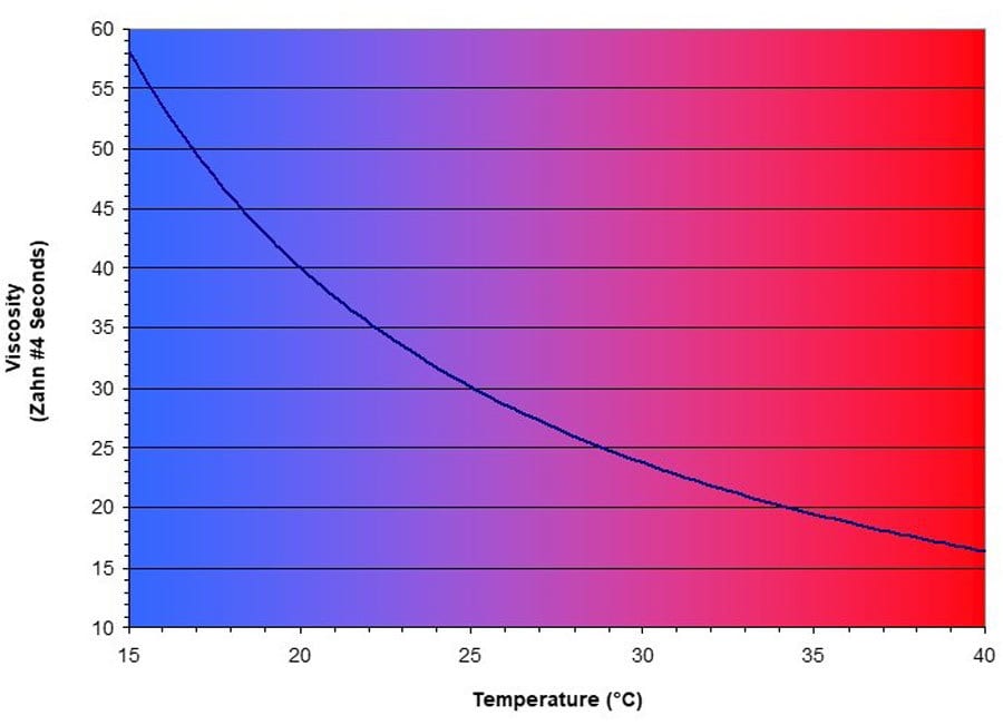
FIGURE 1 ǀ Paint viscosity vs. temperature curve for Valspar 080 White.1
By driving the temperature to, or above, 40 °C (104 °F) our coating is always above the ambient temperature seen year-round (and so always in the heating mode), and also in the flattest portion of the curve where small changes in temperature have the least impact on viscosity. It makes perfect sense.
The problem is that the temperature you need to apply at is the one that produces the optimal film build, coverage, color, adhesion, gloss, finish quality, (i.e., orange peel), etc. Valspar recommends that this specific paint be applied at a viscosity of 26 ± 2 seconds, as shown in Figure 2. We can see that this correlates to a 3 °C window from 26.5 °C to 29.5 °C (80 °F – 85 °F). If the paint temperature is outside of this narrow window, it will be outside of its optimal viscosity range, and performance will suffer.
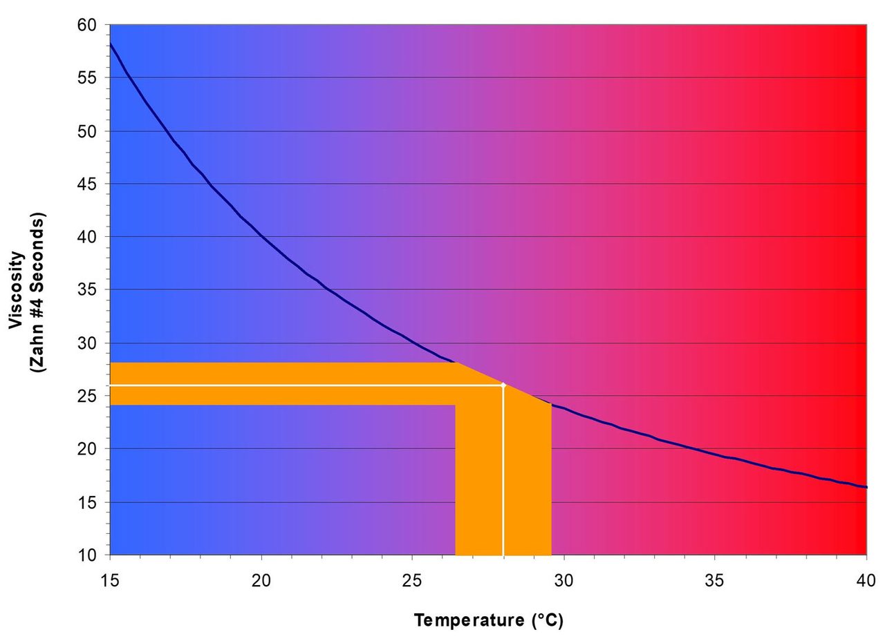
FIGURE 2 ǀ Paint viscosity vs. temperature curve for Valspar 080 White with target viscosity range.1
Driving the temperature up results in a low viscosity, which makes it difficult, if not impossible, to build acceptable film thicknesses and coat sharp edges. It also creates flow issues — especially on vertical surfaces — resulting in run and sag defects.
Elevated temperatures also cause solvents to evaporate more rapidly. This can result in dry spray, reduce flow-out and set times, which can reduce gloss and increase orange peel. Moreover, it increases cost as more solvent must be added to counteract the effects of this evaporation. This runs counter to the concept of increasing temperature to reduce the need for solvents in the first place.
Elevated temperatures can even damage sensitive formulations like Fluoropon, PVDF, Kynar, PVC and plastisols, causing them to crosslink prior to application. They can cause 2K materials to cure at a faster rate, reducing flow-out, set time and pot life.
So, the first thing to know is that the fundamental concept on which your electric heating system is based does not support the needs of your modern coating formulations.
2. Electric Heaters Can’t Cool
An important, but often misunderstood fact regarding viscosity is that every coating formulation has its own unique temperature/viscosity relationship. Figure 3 shows the plots for seven colors, all of the same resin base type and formulated for the same application. But contrary to popular belief, these “identical” coatings display a range of viscosities from 21 to 31 seconds at 25 °C (77 °F), and each varies quite differently over the 10 °C – 35 °C (50 °F – 95 °F) temperature range. To obtain acceptable performance from each color, there must be either changes in the setup parameters of the application system to compensate for these viscosity variations, or the coating must be consistently delivered to the point of application at its optimal temperature. This is usually somewhere in the middle of the curve (where it is the steepest, of course!). In short, this means that it is necessary to cool when it is hot (like summer afternoons) and heat when it is cool (like nights and winters).
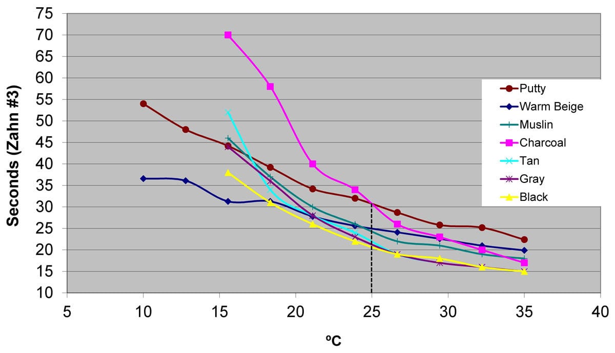
FIGURE 3 ǀ Paint viscosity vs. temperature by color.2
3. Where You Place the Heater Matters
It is commonplace to wrap a heating blanket around the source drum or to place an in-line heater between the pump and the application. It makes sense, as these are easy points of access. But this places too much distance between the heat source and the point of application. Figure 4 shows a thermal model we created for a typical robotic spray system. It allows you to enter a host of variables (resin properties, and ambient and header temperatures) and see how they impact the temperatures (and therefore the viscosities) throughout the system. But there is only one temperature that ultimately determines the outcome. The point of application — as highlighted by the red arrow.
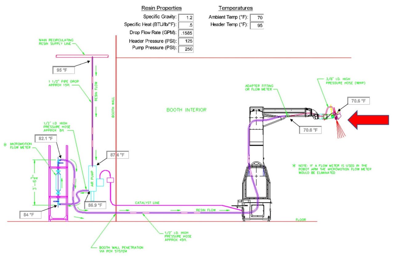
FIGURE 4 ǀ Thermal model for typical spray system.3
Let’s assume that the in-line heater is in the header just before we reach this drop (it could just as well be right in the drop as it leaves the header — and often is!). We can see that it is heating the paint to 95 °F (35 °C). But we are in a 70 °F (21 °C) ambient environment, so all along the path to the robot the paint is losing temperature — moving toward ambient. In this particular instance, the paint comes within 1 °F of ambient at 70.6 °F.
All of the hard work that the heater did (and that you paid for in the form of electricity) was lost by the time that the paint reached the part. It is as if there were no heater in the system at all! The reason this happens is that the heater needs to be placed too far from the point of application. This is because electric heat has high energy requirements, which makes it difficult and expensive to implement in explosion-proof environments.
A good example is shown in Figure 5, where two in-line heaters have been installed on a 2K paint system inside the booth.
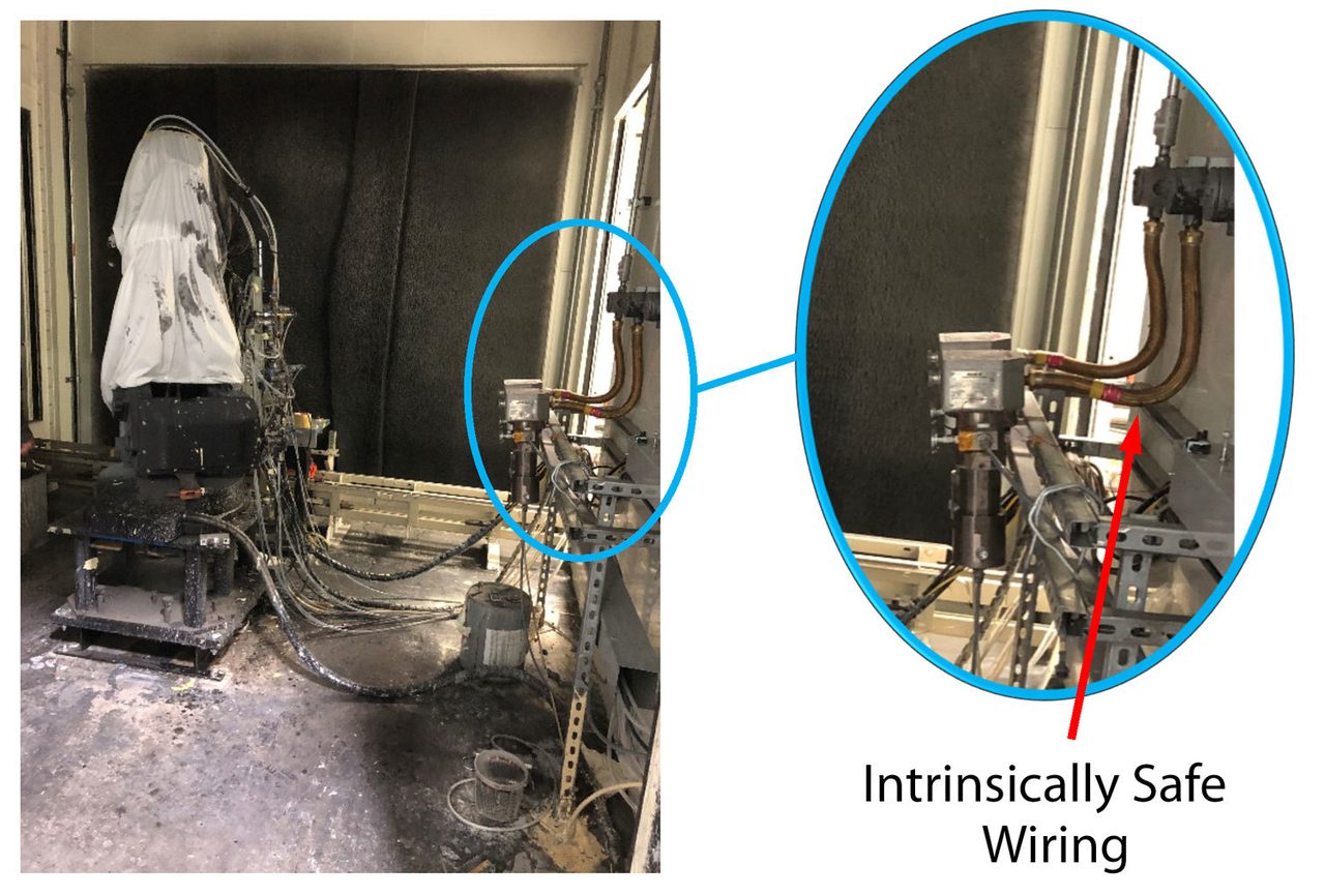
FIGURE 5 ǀ In-line heaters mounted in an intrinsically safe paint booth.4
Another common solution is to mount the in-line heaters on the outside of the booth wall where intrinsically safe wiring is not necessary, as shown at right in Figure 6. While this solves the issues and cost associated with the intrinsically safe power wiring, it places the heat source even further from the actual point of application.
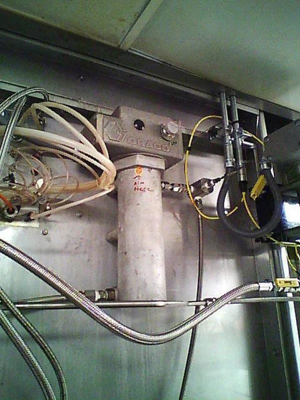
FIGURE 6 ǀ In-line heater mounted on outside of paint booth wall.5
So, why is this an issue?
4. The Heater Setpoint Isn’t the Application Temperature
As the model above shows, the temperature of the coating when it leaves the heater is not the same as it is when it gets to the point of application. But how much it varies is based on multiple factors. Obviously, changes in the ambient temperature from morning to evening and season to season is the first thing that comes to mind, but the ambient around the path through which the coating travels also changes, depending on both the routing that the piping follows and the materials in that path. For instance, if the path is “up and over” running in the truss level, it will be exposed to higher temperatures. Conversely, if it is routed through a trench or basement, it will be exposed to cooler temperatures. And the impact of those temperatures is determined by the composition of the coating path components. For instance, is it comprised of steel tubing or hoses? Is it insulated? Everywhere? Including the fittings, filters, regulators, flow meters, etc.?
Then there’s the question of how many times the coating is exposed to these conditions. Does it flow direct to the robot and stop in a dead-end configuration, or does it recirculate? And if it is recirculating, does it recirculate at the robot or just to the drop? This determines how long the coating can sit in the ambient surroundings before it is applied — an important factor in determining the temperature (and therefore the viscosity) when it is applied.
Conclusion
It’s clear that, though common in their implementation, there are many issues with in-line electric heaters that must be understood and managed if you are going to get stable, predictable performance out of your coating application system. In next month’s final installment of this article, we will examine the next four important considerations, with a specific focus on the impact of electric heat on spray performance and ending with the worst “little-known-fact” that may be costing you hundreds of thousands of dollars a year!
References
1 Paint Temperature vs. Viscosity data provided courtesy of Alsco Metals Corporation – Roxboro, NC.
2 Paint Viscosity vs. Temperature data provided courtesy of Sherwin-Williams Corporation.
3 Spray System Thermal Model provided courtesy of Saint Clair Systems, Inc.
4 Electrically Heated 2K Paint System Photos courtesy of CFAN – San Marcos, TX. (Note: This has since been replaced with a modern heat/cool system.)
5 Source withheld by request.