Ready to proof -- Niki 08/09/23
CB proofed 8/11 - left comments for Niki below
KJ proofed on 8/11 - I have no more changes,
Encapsulation of Silicone Additives for Increased Compatibility and Long-Term Effects
Credit: NiseriN, via Getty Images.
WINNER OF THE PCI AWARD FOR TECHNICAL EXCELLENCE
AT THE 2023 WATERBORNE SYMPOSIUM
By Dr. Sebastian Weiß and Dr. Marc Eberhardt, BYK, Germany; and Prof. Dr. Martin Möller, DWI, Leibniz-Institut for Interactive Materials, Aachen, Germany
In living organisms, compartmentalization facilitates the separation of molecules that normally would intermix or react with one another. In addition, such compartments also offer the possibility of combining components on a small scale that would otherwise segregate macroscopically. Fundamental examples include closed-cell foams and sponges1 and controlled-release applications.2 Controlling the transport of molecules through the wall of such compartments creates the potential for materials with time-dependent and reactive properties. Prominent examples are self-healing materials,3 as well as the mobility through the turgor effect, which was described for plants. This implies that compartmentalization can be a potent tool for materials engineering, yet developments are often still in the early stages. The spatially controlled incorporation of fluids and components requires the process of encapsulation or else the formation of a cellular structure. Capsules in various sizes as well as open- and closed-cell foam structures have been developed on the basis of a wide variety of polymeric materials and have achieved great commercial success in various fields of application.4 However, the size of such cells is usually in the range of a few micrometers, and smaller structures are not accessible. The comparison with natural materials illustrates the significance of much finer cell structures, yet simultaneously the macroscopic homogeneity of a material necessitates the use of capsules with diameters in the submicron range.5 Enabling optical transparency and good resistance of the capsules to shear forces and compression during processing can only be achieved with capsules of such small size. In nature, compartmentalization is typically obtained on basis of self-assembled cell membranes, e.g., lipid bilayers, capsid-forming protein complexes, and primary cell walls of plants composed of polysaccharides.6
Synthetic microcapsules, on the other hand, are formed and filled by the dispersion of two immiscible liquids and the formation of a solid wall at the interface. As a result, the minor component is efficiently encapsulated. The reduction in the size of such capsules cannot be easily tuned to the submicron range. One way to achieve nanometer-sized capsules is the use of significant amounts of surfactants and energy-consumptive mechanical shearing.7 Excessive use of surfactants can be detrimental, especially in coating applications, therefore we have developed a silica precursor that enables formation of silica capsules without the use of any conventional surfactants.8-10 The key issue of this encapsulation approach has been that the precursor turns into a surfactant itself during hydrolysis, thereby efficiently reducing the interfacial energy between dispersed and continuous phase. Uniform capsules with submicron size filled with high-molecular polydimethylsiloxane (PDMS) were accessible using this procedure, however, only when using ultra-high-shear methods like homogenization. Within this work, we present an elegant and industrially feasible way to prepare silica nanocapsules using conventional shear methods like a rotor-stator dispersion process.
Practical relevance of such capsules was demonstrated by the example of a completely transparent clearcoat filled with capsules. By releasing the encapsulated substance in a targeted manner, this approach can provide a universally compatible form of application for silicone oils, which normally have to be laboriously modified for use with different coating systems. On the other hand, a reservoir of silicone can be established within the coating, which is intended to produce more long-term surface effects.
Results and Discussion
Hyperbranched polyethoxysiloxane (PEOS) has been used to encapsulate various substances in oil-in-water (O/W) as well as water-in-oil (W/O) dispersion processes.8-10 Due to the hyper-branched character of the polymer, a high number of reactive surface groups are present. During emulsion, part of the ethoxy groups on the surface will hydrolyze and transform into silanol groups, giving the molecule an amphiphilic character. This typically occurs at the interface between oil and water, where continuous hydrolysis and condensation of the polymer leads to the formation of a solid silica shell. The minimum interfacial tension (IFT) in this process is observed after several minutes, thus preventing rapid formation of ultra-small droplets, e.g., by application of light shear force. A practical and elegant solution to enhance the interfacial activity of PEOS is the modification with polyethylene glycol monomethyl ether (PEOS-PEG), which may result in water solubility and very strong amphiphilic properties.11 Based on the large proportion of hydrolyzable surface groups in PEOS, the level of modification, and correspondingly the amphiphilicity, can be accurately manipulated over a wide range. The goal here is to exploit these properties in the surfactant-free encapsulation of polydimethylsiloxane (PDMS) to attain minimum capsule diameters with narrow size distributions. Figure 1 shows the reaction route to the so-called PEOS-PEG.
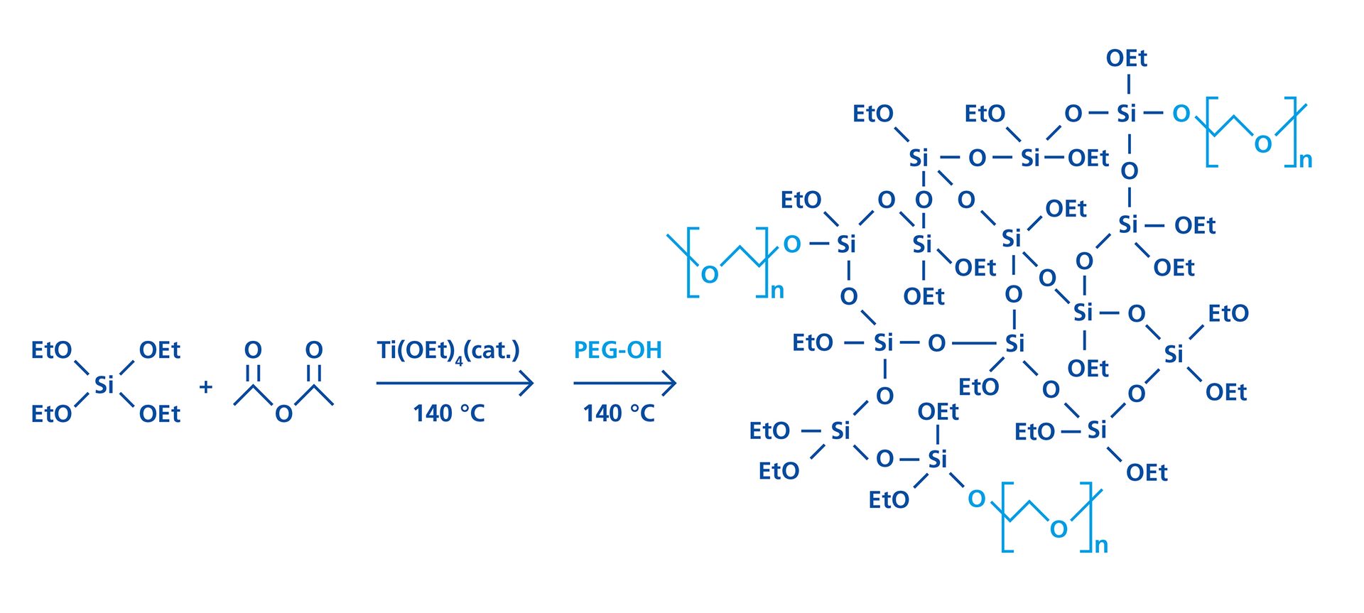
FIGURE 1 ǀ Schematic reaction using TEOS and acetic anhydride to form PEOS, and its subsequent transesterification with polyethylene glycol monomethyl ether to yield PEOS-PEG.
PEOS-PEG with PEGylation modification degree between 5% and 20% of PEG (350 g/mol, percentage of ethoxy groups replaced by PEG, e.g., in case of 10% substitution: PEOS-PEG-10) were prepared and the IFT between the silicon oil/water interface stabilized by the PEOS-PEG compounds was recorded using the spinning drop technique.12 Silicon oil with low viscosity of 1.5 centiStokes (cSt) was selected for the measurements to grant precise results and avoid viscosity-related retardation effects.
Figure 2 illustrates the IFT observed employing 2 wt% of PEOS-PEG compounds with different modification degrees. Interestingly, the lowest value of the IFT was usually recorded directly after the onset of the measurement, and originated from the intrinsic amphiphilic nature of the compounds. Cleavage of PEG chains results in an increasing IFT over time.
A higher PEG content lowers the IFT until a minimum is reached at approximately 10-12% molar substitution with PEG. Above this value, the increased water solubility causes an increase in IFT. For example, the IFT in PEOS-PEG-10 is 0.28 mN/m. In contrast, traditional surfactants like sodium dodecyl sulfate (SDS) show values of about 10 mN/m,demonstrating the outstanding stabilization of the silicone/water interface by such polymers.13
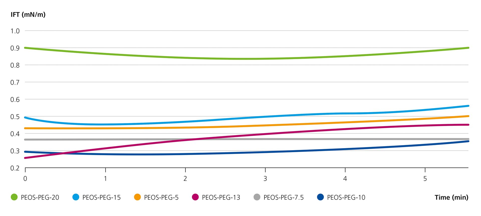
FIGURE 2 ǀ Interfacial tension between a drop of silicon oil with a viscosity of 1.5 cSt and water with the addition of 2 wt% PEOS-PEG compound with different PEG-modification degrees, measured at room temperature by spinning drop technique.
In the next step, the highly surface-active PEOS-PEG was used for the encapsulation of silicon oils. For this, silicone oil and PEOS-PEG were dispersed in water via a rotor-stator dispersion process. After emulsification, the final capsules were obtained by an extended ripening process by stirring the capsule dispersion at 60 °C for 16-24 hours. When using pure PEOS, stable spherical capsules were obtained that were in the range of a few micrometers. With PEOS-PEG-10, the capsules had diameters below 1 µm, however, in the electron micrographs, they appear soft and fragile. As a solution, at the onset of the post-dispersion condensation, the pH was adjusted to approximately 9 to catalyze the condensation and form firm capsules. Figure 3 depicts electron micrographs of capsules with PDMS 2000 (number represents the viscosity in cSt) prepared using the described approach, and the comparable capsules produced with unmodified PEOS.
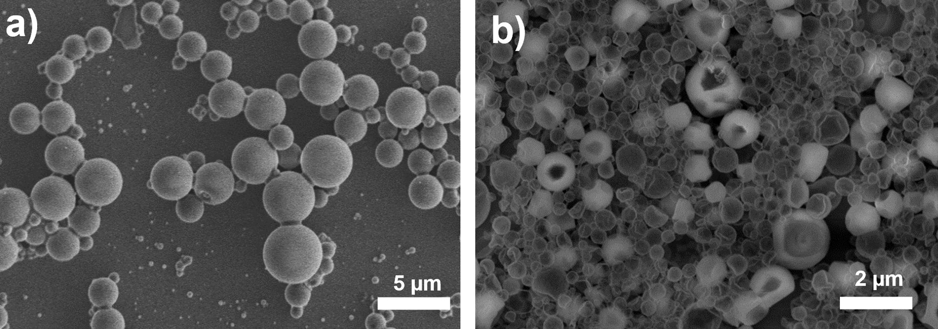
FIGURE 3 ǀ Electron micrographs of encapsulated PDMS 2000, a) unmodified PEOS, b) PEOS-PEG-10 using the rotor-stator dispersion process, utilized as combined surfactant and silica source for the encapsulations.
Adding the prepared capsules to an aqueous clearcoat resulted in coatings with highly inhomogeneous and hazy appearance. Evidently, the size and polydispersity of the capsules needed to be reduced in order to reduce aggregation and scattering of light, which deteriorates optical properties. Another process parameter for droplet formation during dispersion and thus the final capsule size, is the viscosity of the disperse phase. Basically, the droplet size and the difficulty of forming droplets at all, increase with the viscosity. When the ratio of the viscosity between disperse and continuous phase exceeds a certain value, no drop formation at all can be observed by simple shear, as illustrated in Figure 4.
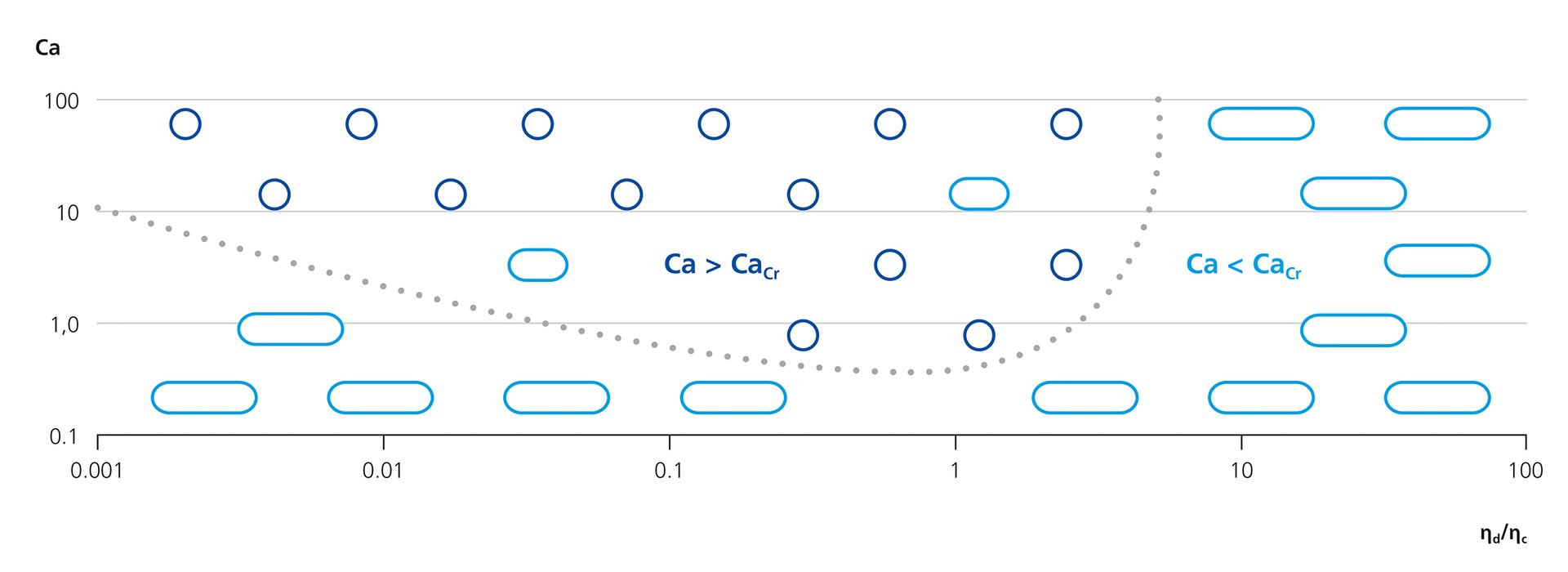
FIGURE 4 ǀ Capillary number versus ratio of continuous (ηc) and disperse phase viscosity with light shear. The dotted line indicates the critical capillary number, Cacr.
This underlying concept is defined as the critical capillary number.14 The overall assertion of this principle is that at a particular viscosity ratio, the capillary number (Ca) must be in excess of a critical value (Cacr) to allow droplet formation to occur.
The capillary number is defined as shown in the following equation:
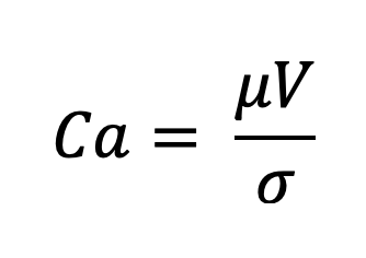
In the equation, µ represents the dynamic viscosity of the continuous phase, V is a characteristic velocity, and σ is the IFT. In Figure 4, this correlation is demonstrated relating to light shear force. If shear rates are increased, e.g., by rotor stator emulsification, the Cacr for droplet creation will adjust to higher values accordingly.
To address viscosity-related effects, alternative dispersion technologies exist, including membrane emulsification, which depends on dilation rather than shear, as well as homogenization, which provide efficient and uniform droplet formation. Yet, such dispersion processes are not widely used in the coatings industry as they are expensive and cannot be easily transferred to large scale. Therefore, they are not considered here.
To overcome the limitation of droplet formation at increasing viscosity ratio of continuous and dispersed phases, we diluted the encapsulant in tetraalkoxysilane with the objective of lowering the viscosity of the dispersed phase. We identified tetraethoxysiloxane (TEOS) as a viable diluent for multiple reasons. In addition to being readily available at low cost, the component also exhibits negligible toxicity. Dilution of silicone oils in TEOS drastically lowers the viscosity. TEOS is fully miscible with PDMS in all ratios. Figure 5 shows the effects of different PDMS2000:TEOS ratios on the viscosity of the mixture, and nicely illustrates that as little as 0.5 equivalents of TEOS can reduce viscosity by an order of magnitude, increasing the efficiency of emulsification processes, and thus providing a tool to improve the encapsulation process. Furthermore, TEOS is a reactive diluent as it readily co-condenses with the silica in the condensation process, thus completely converting into solid material within the process.
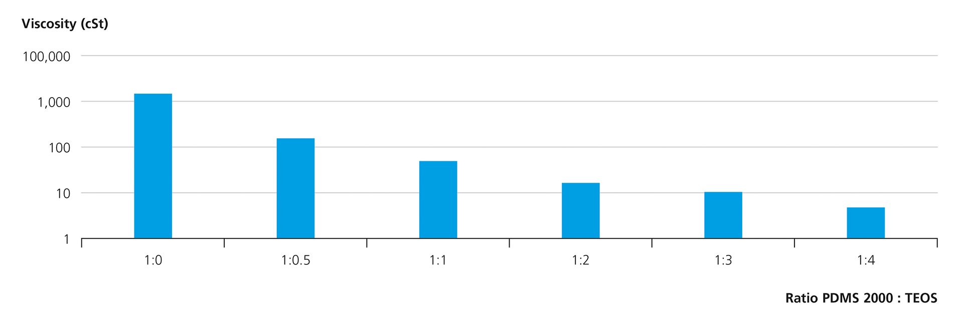
FIGURE 5 ǀ Viscosity of PDMS2000:TEOS mixtures measured at a shear rate of 100 s-1 at ambient conditions using a cone-plate viscometer.
We then measured the interfacial tensions of PDMS 100 mixed with TEOS in different ratios using 2 wt% of PEOS-PEG-10 (Figure 6). PDMS without any TEOS results in an interfacial tension of around 2 mN/m. With increasing TEOS content, the IFT drops accordingly, reaching a value of approximately 0.3 mN/m with a ratio of TEOS/PDMS of 2:1. The interfacial tension with pure TEOS is even lower at around 0.05 mN/m. Hence, the dilution not only decreases the viscosity ratio but also increases the compatibility of the polymeric surfactant with the dispersed phase as evident from the lower IFT values.
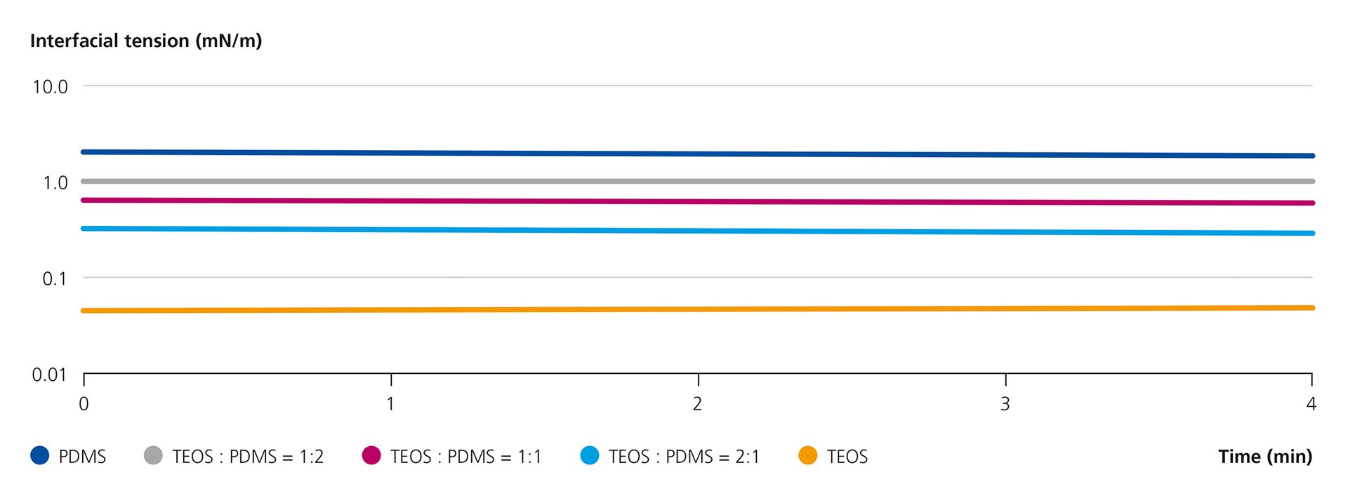
FIGURE 6 ǀ IFT between a drop of PDMS100 with PDMS100:TEOS mixtures in water, recorded with rotating drop technique, using 2 wt% of PEOS-PEG-10.
Based on the low IFT, the encapsulation of silicone oils with PEOS-PEG-10 was performed as follows. First, a mixture of TEOS and the respective silicone oil was added to water containing PEOS-PEG at room temperature, and the whole mixture was dispersed for 10 min via a rotor-stator process. The dispersion was then brought to a pH of 9 using aqueous ammonia, followed by a stirring period at 60 °C for 24 hours to allow the ripening of the capsule shell. Table 1 lists the formulations and capsules diameters obtained.
TABLE 1 ǀ Formulas and capsule diameters for encapsulation of PDMS of different viscosity mixed with TEOS using emulsification by rotor-stator emulsification and PEOS-PEG-10.
General observations are that the average capsule size is in the range of about 200-300 nanometers, which is exceptional for such a dispersion process. In examples 1 and 2, the only change is the ratio of silicone oil to TEOS, but the capsule size remains relatively unchanged. This suggests that some dilution is sufficient to achieve the desired effect of reducing capsule size. Also outstanding is the finding that silicone oils up to the tested viscosity of 60,000 cSt are accessible for encapsulation by means of the process.
Figure 7 shows field emission – scanning electron microscopy (FE-SEM) electron micrographs of several capsule experiments. Evidently, the capsules exhibit a rather homogeneous appearance and appear firm, spherical, and stable. Next to microscopic data, light-scattering data underlines the findings and proves very similar sizes and size distributions for all samples shown. Apparently, the combination of the two factors, i.e., low interfacial tension and adjusted viscosity, helps reduce the capsule sizes by an order of magnitude.
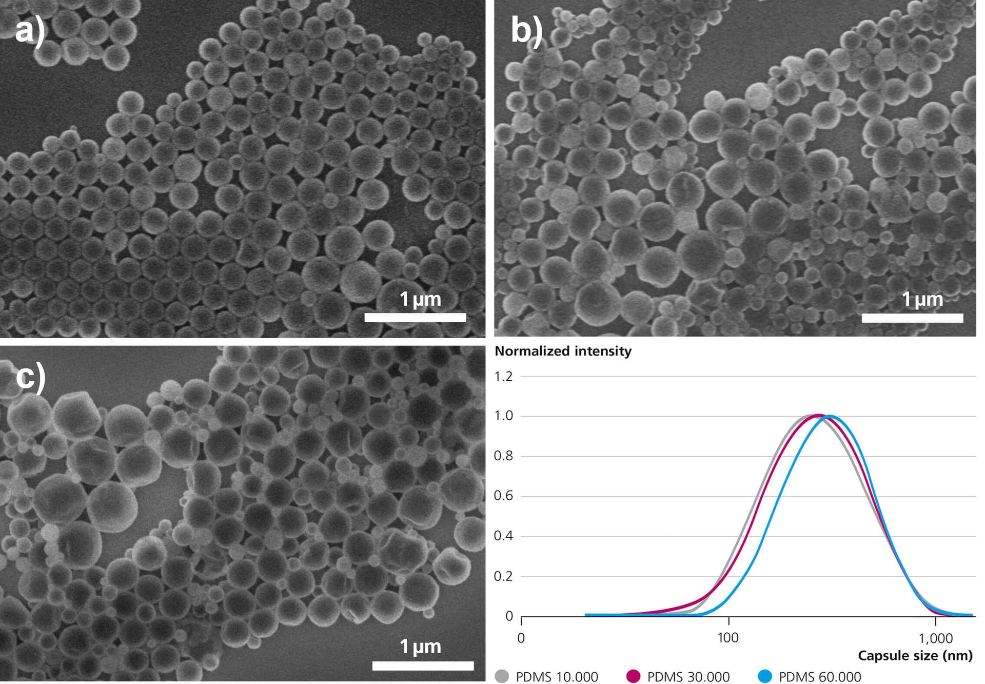
FIGURE 7 ǀ FE-SEM images (a - c) and the capsule size distribution determined from DLS (d) of silica capsules produced with PEOS-PEG and dilution of PDMS with TEOS in ratio 1:2. Emulsification technique utilized was rotor-stator dispersion. Viscosity of PDMS was a) 10,000 cSt, b) 30,000 cSt, and c) 60,000 cSt.
In addition to silicone oils, we have been able to successfully perform the procedure for other highly viscous substances such as hydrophobic polyacrylates, which leads to the assumption that the approach is universally applicable. To obtain more details about the exact mechanism of droplet and capsule formation, we next investigated the size evolution of the dispersions throughout the process. The formation mechanism of the capsule was studied with the aid of light scattering to monitor the size evolution. For the experiment, we used PDMS with a viscosity of 2,000 cSt mixed 1:2 with TEOS and 2 wt% PEOS -PEG-10, analog to Experiment 4 from Table 1. During the rotor-stator emulsification, samples were collected at specified time intervals and analyzed directly by dynamic light scattering (Figure 8).
The initial sample was taken after 30 seconds of emulsification time and revealed a bimodal distribution with average domain diameters of approximately 100 nm and 500 nm. At 1 minute, the bimodal signal remains, however the size of the peak at 500 nm has shifted to 400 nm. After 2 minutes, the peaks have fused into a wide signal, narrowing significantly with a maximum at around 250 nm after the full emulsification time of 10 minutes.
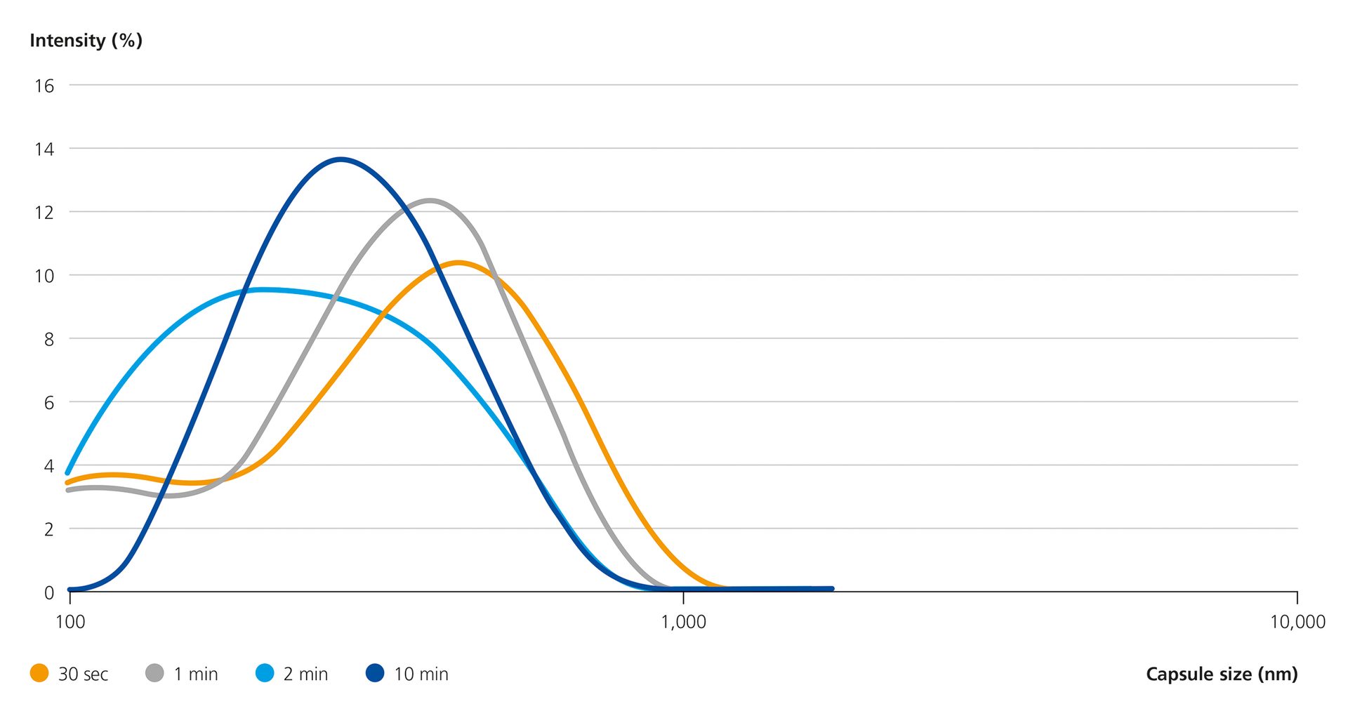
FIGURE 8 ǀ Evolution of capsule size distribution during emulsification of a PDMS 2000: TEOS (1:2) mixture using PEOS-PEG-10 and rotor-stator emulsification, measured by dynamic light scattering.
To interpret these results, it is essential to consider the behavior of the PEOS-PEG compounds in aqueous media during encapsulation (presented schematically in Figure 9). Upon addition of PEOS-PEG to water, self-assembly of the polymer initially leads to the formation of vesicles with diameters of about 100 - 200 nm. Upon addition of the PDMS:TEOS mixture, such vesicles co-exist with significantly larger PDMS:TEOS droplets, which are well stabilized by the PEOS-PEG. Continuous shear stress facilitates breakup of the PDMS:TEOS droplets, while the remaining free PEOS-PEG stabilizes the newly forming interface.
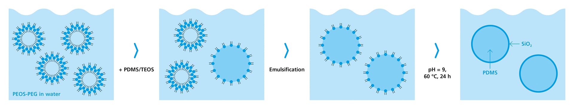
FIGURE 9 ǀ Illustration of the concept of the encapsulation process. PEOS-PEG self-assembles in water (top left); the added PDMS/TEOS mixture is stabilized in the form of small droplets. Upon shear stress (top right), nanometer-sized droplets form (bottom right) due to the ultra-low IFT induced by PEOS-PEG. At high pH and elevated temperature, PEOS-PEG and TEOS solidify to form a firm, continuous silica shell around the silicon oil (bottom left).
Thus, in the terminal state, stabilized droplets are formed, which have a monomodal distribution and a size that lies in between that of the vesicles and droplets during early stage of the dispersion. Throughout this process, the free PEOS-PEG is eventually consumed, and nanometer-sized PDMS:TEOS droplets are formed. About 30 minutes after emulsification, the PEOS-PEG has formed a stable initial layer around the oil droplets. Ammonia was then added to accelerate the conversion of PEOS-PEG and TEOS to the solid silica shell. If ammonia is added immediately after emulsification, highly wrinkled capsules are obtained because a rigid outer capsule layer is quickly formed, which subsequently deforms as the oil phase shrinks when its interior condenses.
To investigate its compatibility with coatings, capsules were incorporated into a coating formulation both in dried-powder form and as an aqueous dispersion. The coating selected was a clearcoat based on a polyurethane-polyacrylate binder used in the automotive industry. In the case of powdered capsules, complete dispersion of the capsules could not be achieved, leaving capsule aggregates that resulted in a very inhomogeneous capsule appearance. Capsule dispersions, on the other hand, could be incorporated without difficulty and resulted in a completely homogeneous coating (Figure 10). Figure 10a shows the coating where the PDMS 2000 was introduced in free form into the coating. Strong cratering is observed as the silicone oil causes differences in surface tension. This is a general problem in the coating industry, as cratering may render components unusable. Typically, polysiloxanes are modified in various ways to increase compatibility. In this case, however, encapsulation is used to create a universal solution for various coating systems. Figures 10b and 10c show coating films with 0.1 wt% encapsulated PDMS 2000 with an average capsule size of 250 and 350 nm. With 250 nm capsules, a completely transparent coating is obtained, while with 350 nm capsules, a haze is observed due to light scattering.
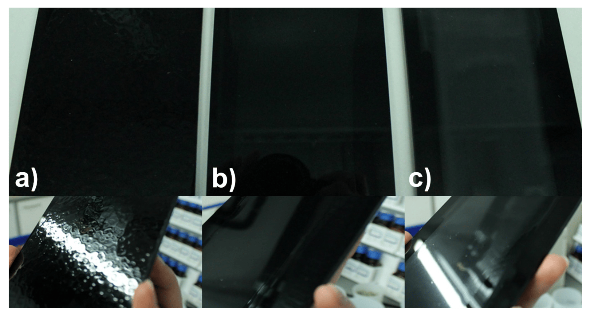
FIGURE 10 ǀ Aqueous clearcoats based on polyurethane-polyacrylic binder. In a) 0.1 wt% PDMS (2000 cSt) was added to the formulation. In b) and c), 0.1 wt% encapsulated PDMS (2000 cSt) with average diameters of 250 nm (b) and 350 nm (c) were added in the form of an aqueous dispersion.
In summary, the encapsulation method is ideally suited to encapsulate silicone oils and thus create compatibility in normally incompatible systems. This is enormously important, especially in the formation of a coating surface, to avoid cratering. The capsule size has a decisive influence on the optical properties, it could be shown that capsules accessible by the developed process lead to transparent coatings.
For comparison in its free and encapsulated form, application tests of a conventional surface additive in both delivery forms were conducted in the waterborne clearcoat (Table 2). For this purpose, the clearcoats were applied onto black polycarbonate sheets to best represent the optical properties of the coatings. Compared to the coating without surface additive, the surface tension was significantly reduced from 30 mN/m to ~ 22.5 mN/m in both examples. In the visual evaluation for crater formation, it is noticeable that craters are only present when the silicone additive is introduced in free form. Similarly, the leveling of the coating is significantly inferior with free additive. The haze of the coatings is ok in all cases, with a slight drop in the coating with free additive. Additionally, the coefficient of friction is clearly lowered in both cases with added additive, suggesting the presence of a silicone layer on the surface. These results clearly show that compatibility can be achieved by means of encapsulation, since detrimental surface defects are prevented during surface formation. Nevertheless, during coating cure, some of the capsule content seems to have leaked out, as the typical induced properties comparable to the sample with free additive can be observed.
TABLE 2 ǀ Properties of aqueous clearcoat with and without encapsulated alkyl-modified silicone additive.
* capsule amount was adjusted to incorporate 0.1% of encapsulated additive in the coating
**visual grading, 1 – best, 5 – worst.
***alkyl-modified silicone oil
Conclusion
Within this work, we developed a surfactant-free process for nanoencapsulation. The focus here was on encapsulation of especially polydimethylsiloxane of various molecular weights, serving as a model substance for surface additives. The three critical parameters that impact the droplet formation process and thus the resulting final capsule diameters are the dispersion energy, the interfacial tension, and the viscosity ratio of the continuous and disperse phases. Given the technical impracticality of high-energy dispersion tools, we targeted the interfacial tension and viscosity ratio in this effort. To minimize interfacial tension, we modified the hydrophobic, hyperbranched polysiloxanes using monofunctional polyethylene glycols. This induces an intrinsic amphiphilicity and led to superior stabilization of droplets at interfacial tensions close to zero. We have observed that rapid and effective formation of ultra-small droplets is viable if the viscosity ratio between the dispersed phase and the continuous phase does not exceed a certain value (about 100). Viscosity control of the disperse phase via addition of TEOS was the key issue in allowing the formation of ultra-small capsules. Not only does TEOS reduce the viscosity of the dispersed phase, its incorporation also decreases the interfacial tension further and thus facilitates the formation of small droplets. Additionally, TEOS also works as a silica source and helps to reduce the amount of incorporated hyper-branched silica precursor. The combination of ultra-low interfacial tension and reduced viscosity of the disperse phase allows for the synthesis of capsules with diameters 200 to 300 nm, if the industrially feasible rotor-stator emulsification is employed.
Other emulsification techniques like ultra-sonication can even offer further reduction in capsule diameter. These capsules were demonstrated to be suited for incorporation into clearcoats without inducing perceivable turbidity or surface defects of the coatings and present a convenient way to introduce incompatible substances to a coating without surface defects. Application results indicate that surface effects of the additives can also be achieved when the additives are incorporated in the encapsulated form. A reservoir of silicone additive is thereby created inside the coating, allowing for long-term effects. Such effects need to be studied in the next step. We imagine that encapsulation of additives will play an important role in the future of coatings technology, from technological as well as sustainability aspects.
Materials
Tetraethoxysilane (TEOS, GPR RECTAPUR, VWR), acetic anhydride (ACS reagent,
≥ 98.0 %, Sigma-Aldrich), PDMS1.5 (Sigma Aldrich), PDMS100 (VWR), PDMS2000 and PDMS10000 (Wacker), PDMS30000 and PDMS60000 (Gelest), titanium tetraorthosilicate (Ti(OEt)4, VWR). Deionized water was used for all experiments.
Methods
Synthesis of PEOS and PEOS-PEG
PEOS-PEG was synthesized in a one-pot reaction consisting of tetraethoxysilane, acetic anhydride, and a catalytic amount of Ti(OEt)4 at 135 °C. Subsequent transesterification with polyethylene glycol monomethyl ether (350 g/mol) led to the PEGylated PEOS compound. This synthesis was previously reported in literature.15 The resulting PEOS-PEG is typically characterized by the molar fraction of ethoxy groups replaced by PEG, i.e., PEOS-PEG-10 for replacement of a molar fraction of 10% ethoxy groups by PEG.
Preparation of PDMS@SiO2 Capsules by Ultra-Turrax
In a typical procedure, 0.7 g of PEOS-PEG compound was added to 80 g of distilled water at 25 °C and shaken to obtain a homogenous opaque mixture. Then, 0.7 g PDMS or PDMS:TEOS mixture was added, and the mixture was emulsified with an Ultra-Turrax® T25 at 18,000 rpm for 10 minutes. The dispersion was then transferred to a round-bottom flask and stirred vigorously on a magnetic stirrer at 60 °C for 24 hours. After 30 minutes, the pH was adjusted to 9 with ammonia. The resulting capsules were centrifuged for 25 minutes at 16,000 g, and the white precipitate was separated, and either re-dispersed in water or freeze-dried to yield a white powder.
Field Emission - Scanning Electron Microscopy (FE-SEM)
FE-SEM and STEM measurements were performed on a Hitachi S4800 or SU9000 high-resolution field emission scanning electron microscope with an accelerating voltage of 1.5-30 kV. Before the measurements, the capsule dispersion was diluted to the desired concentration, deposited on the silicon wafer (FE-SEM) or a formvar-carbon-coated copper grid with 200 meshes (STEM), and air-dried under ambient conditions.
Interfacial Tension
Interfacial tension between water and silicon oil phase was measured at room temperature with a Krüss spinning drop tensiometer. A droplet of silicon oil with 2 wt% PEOS was placed in the glass capillary and rotated at 6,000 rpm. The IFT was calculated either with the method after Vonnegut or Young-Laplace.
Particle Size Measurements
Particle size in water was determined by light scattering measured either with a Malvern Zetasizer Nano Series or with a Mastersizer 2000. Zetasizer measurements were only used for particles with an average diameter below 500 nm. Measurements were conducted at 25 °C. When using a Zetasizer, measurements were conducted at a scattering angle of 173°. Before measurements, the dispersions were diluted to a particle concentration of 1 wt%.
Rheology
The rheological experiments were performed using Dynamic Hybrid Rheometer 3 (DHR3, TA Instruments) with 40-mm plate – plate geometry. After 60 seconds equilibration time, the mixtures were analyzed via controlled shear rate, stress range of 0-20 Pa, and rate range of 0-100 s‑1.
Preparation of Clearcoats
Waterborne clearcoats were prepared using a KPG stirrer according to the following procedure. NeoPac E 180 (90.5 g) and 0.1 g BYK-425 were stirred for 5 minutes at 1,000 rpm. Then, 4.1 g butyl diglycol and 4.1 g of capsule dispersion (24.5 mg PDMS per mL for 0.1 wt% silicon oil in the coating) were premixed, added, and stirred for 5 minutes at 1,000 rpm. Thereafter, 1.0 g BYK-028 was mixed in for 3 minutes at 2,000 rpm. A drop of diethanolamine was added, and the coating formulations were stored overnight to release any residual air bubbles. The waterborne coatings were applied to polycarbonate plates using a drawdown rod (100 μm wet film thickness) and dried at room temperature for 24 hours. The thickness of the dry films was in the range of 50–65 μm, as determined by a thickness gauge.