Credit: SylvieBouchard / iStock via Getty Images Plus
A New Way to Visually
Evaluate Color
By Werner Rudolf Cramer, Muenster, Germany; and Wolf Moritz Cramer, Hamburg, Germany
For effect colors and pigments, portable multiangle measuring instruments are generally used. At a fixed illumination of 45°, measurements are taken from the gloss angle at several different angles. Originally, these geometries were selected for paints or plastics formulated with aluminum pigments. Meanwhile, interference pigments were measured using the same geometries. Although they differ significantly from aluminum pigments in terms of their appearance, the same classical geometries are used to measure them. Furthermore, discrepancies between visual and instrumental assessment geometries also occur during visual matching. On the one hand, this is because geometries of visual and instrumental assessment do not match. On the other hand, the instruments lack geometries with which modern interference pigments can also be analyzed. Experimental instruments such as GonioViewer Experimental bridge these discrepancies with their geometries and support the visual inspection of effect pigments.
How the Rainbow Becomes Visible
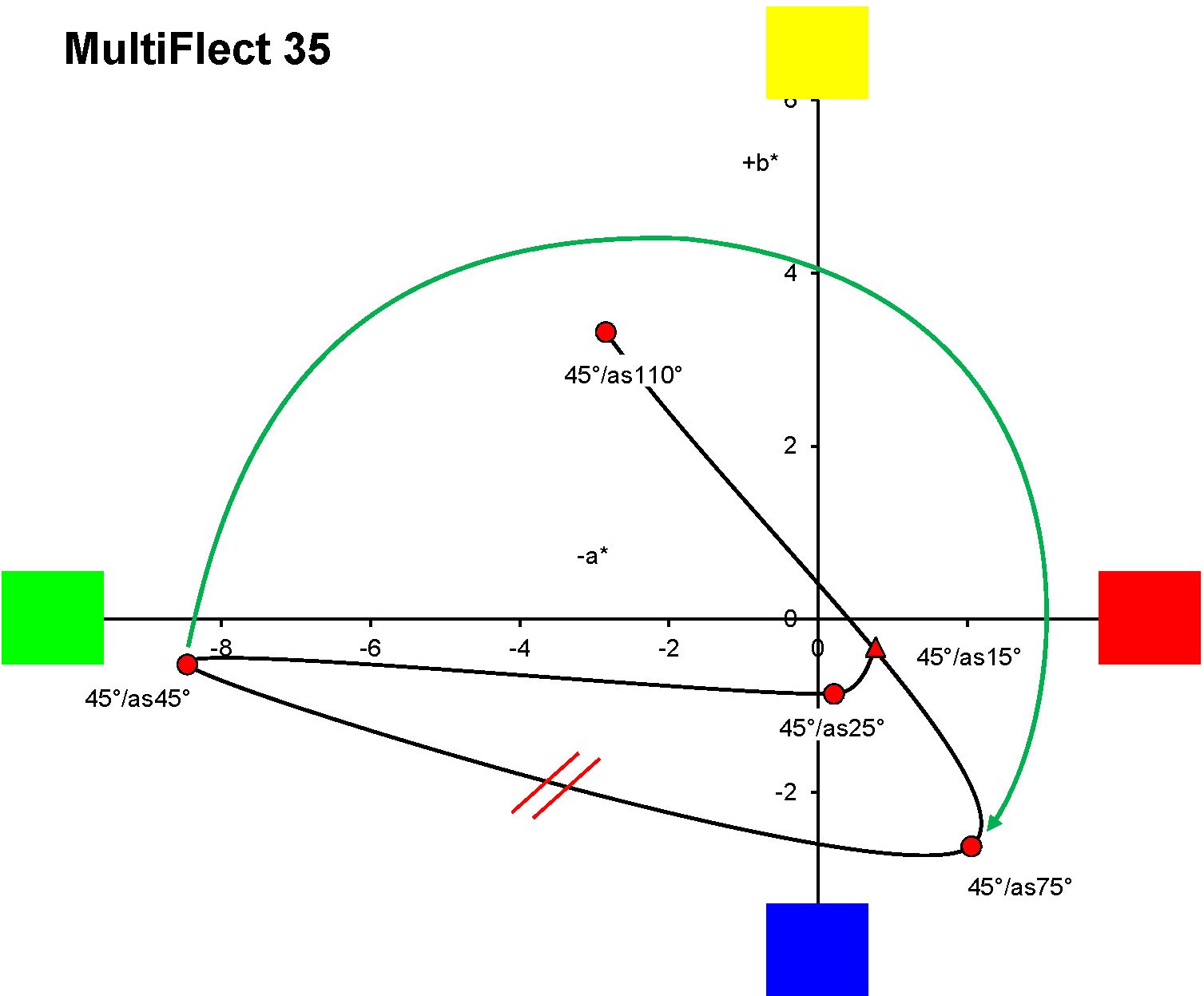
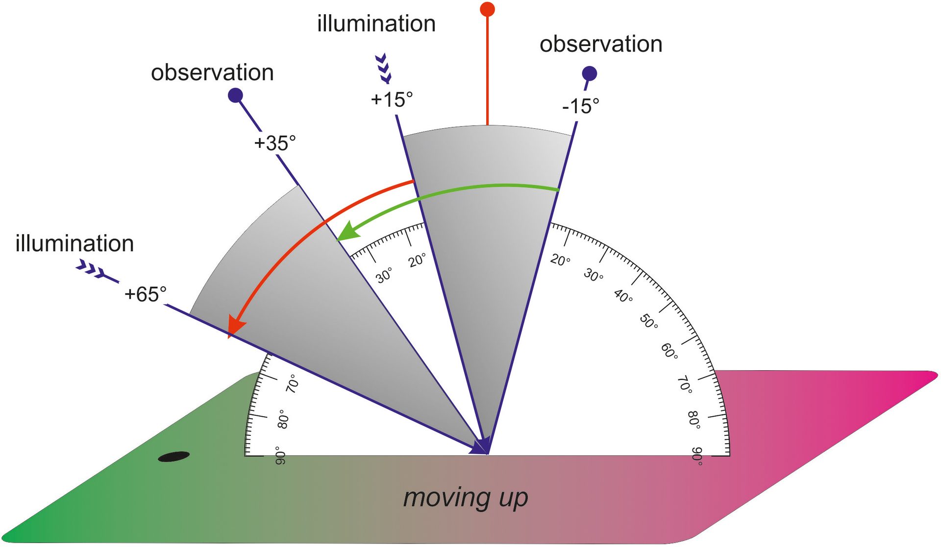
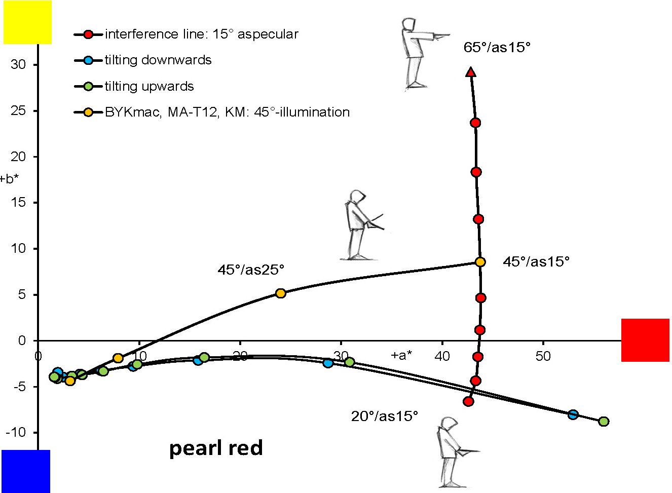
New interference pigments show a color gradient like that of a rainbow. This gradient starts at 30° from the gloss angle with blue-violet, continuing through blue, green and yellow to red at 75° from specular. The current measuring instruments measure at 25°, 45° and then at 75° from the specular, i.e., the measured values show the color gradient from blue-green to red. The other gradient colors are not captured, although they can be observed visually (Figure 1).
FIGURE 1–ǀ–The arc marked in green reflects the true color gradient of the pigment as observed with GonioViewer 01; the connecting line of the measuring points only partially shows the gradient.
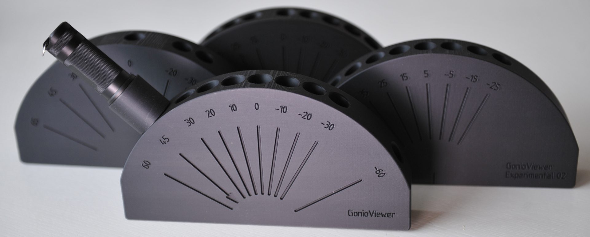
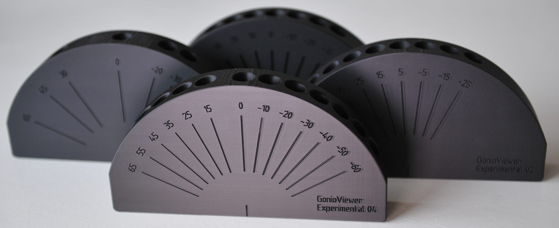
The GonioViewer Experimental 01 was created to ensure the visual assessment of these pigments. Like the other GonioViewer Experimental, it is manufactured using 3D printing and measures 23 cm in width and 16 cm in height. Drill holes on the 4 cm-wide half sphere enable illumination and observation. One or two sample sheets can be positioned under the GonioViewer to make comparative observation possible (Figure 2).
FIGURE 2–ǀ–GonioViewer 01 adapts to visual sampling needs, adding geometries that close the gap between visual inspection and current measuring instruments.
The GonioViewer Experimental 01 allows the color gradient to be visually recognized in precisely defined geometries. Comparative measurements were taken with the Zeiss GK311/M. This measures at different illumination and observation angles, which can be set independently of each other in 5° steps.
Exact Angles When Testing at the Window
When a panel is viewed at a window or in a light booth, geometries are assumed that do not correspond to any geometry of the portable measuring instruments.
The panel — either on its own or with a comparison panel — is tilted up and down. The starting position is the view into the gloss on the panel the angle of which results from the angle of illumination. Perpendicular to the panel, the normal lies between the two.
If the angle of illumination in the starting position is 15°, for example, the panel is observed at -15°. The angle of difference of 30° between the two positions remains the same during the entire observation, i.e., the position of the illumination and the position of the observer do not change (Figure 3).
FIGURE 3–ǀ–Tilting the panel downward changes the illumination and observation angles, but the angle between them remains constant during visual assessment.
If the panel is tilted downwards, the normal moves in the direction of the illumination and the illumination angle becomes smaller. Accordingly, the specular angle also becomes smaller. If the illumination angle is 5° and the specular angle is -5°, the panel is observed at -25° (5° illumination minus 30° angle between illumination and observation equals -25°, observation equals -20° from the specular angle = aspecular). The observation is on the side of the specular angle that is opposite the illumination (trans position). If the panel is tilted further downwards, the illumination first moves into the normal and then to the other side of the normal. Accordingly, the gloss angle (specular) also changes sides to the normal (cis position = illumination and observation are on the same side relative to the gloss angle).
Due to the optical law of the reversal of light, the illumination and observation can be swapped. If you then compare the geometries when tilting up and down, these geometries are the same, i.e., the same geometries are adopted when tilting up and down. It therefore does not matter whether you tilt the panel up or down.
GonioViewer Experimental 02 has holes for observation at windows from -25° to 75° in 10° steps. Starting from a difference angle of 30° (15°/-15° illumination/observation) or 50° (25°/-25°) for overhead adjustments, the color gradient can be observed at a precise angle.
As Accurate as the Measuring Instruments
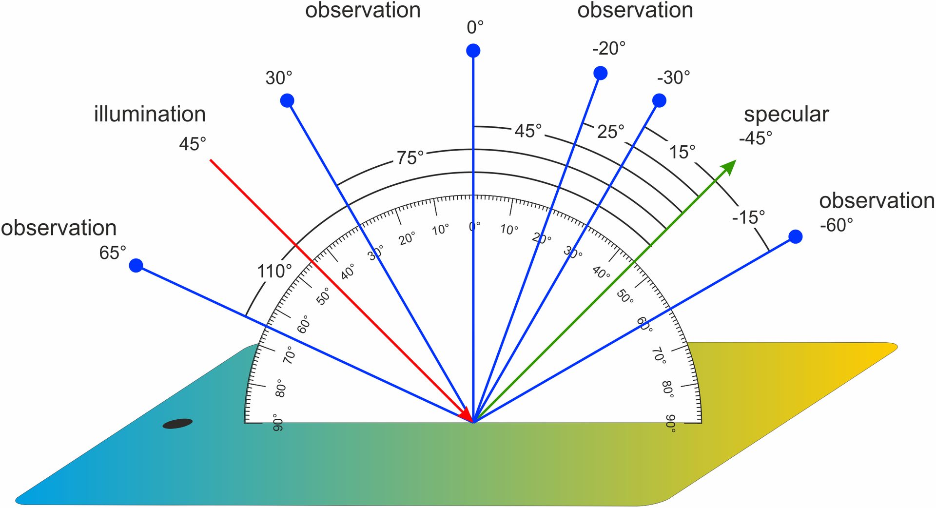
The angles of the holes in this instrument correspond exactly to the angles of the current multiangle instruments: illumination occurs at 45° and observation occurs at -15°, 15°, 25°, 45°, 75° and 110°.
In 2008, the ASTM (American Society for Testing and Materials) defined additional geometries as standards for measuring interference pigments. The conventional angles, which were defined arbitrarily, were joined by a second illumination at 15° and a measuring angle at -15° from the gloss angle. These angles were published by the author in the early 1990s based on numerous experiments (Figure 4).
FIGURE 4–ǀ–Standard angles currently used in all portable multiangle measuring instruments.
The GonioViewer Experimental 03 has two advantages: When observing and assessing a panel — for example, the size of a postcard — there is an angle of about 15° between its upper and lower edges. This angle is larger than the two measurement angles close to gloss. Our eye is deceived by color gradients and cannot recognize color differences in a gradient. Our visual impression is based on the large area of a panel as opposed to the small measurement field. The GonioViewer Experimental 03 solves this problem with its small and precisely angled observation area.
How the Interference Becomes Visible
This GonioViewer offers geometries that are assumed by an interference when viewed visually. The panel is viewed with outstretched arm under flat illumination. Then the panel is moved downwards in parallel, with the illumination being changed to steeper. The panel is always viewed close to the gloss at 15°. This procedure corresponds to the interference law, which describes the dependence of the color on the angle of the incident light.
The holes in the GonioViewer Experimental 04 are at angles of -60° to 65°, so that observation takes place, for example, at 0° with an illumination of 15°. The illumination then changes in 10° increments up to 65° from the normal. The observations are also made in 10° increments from 0° to -50°. Here, too, the panel is observed with pinpoint accuracy and at the exact angle (Figure˜5).
FIGURE 5–ǀ–GonioViewer 04 enables precise angular observation by allowing panels to be viewed close to gloss while following the interference line.
Point- and Angle-Accurate Assessment Possible
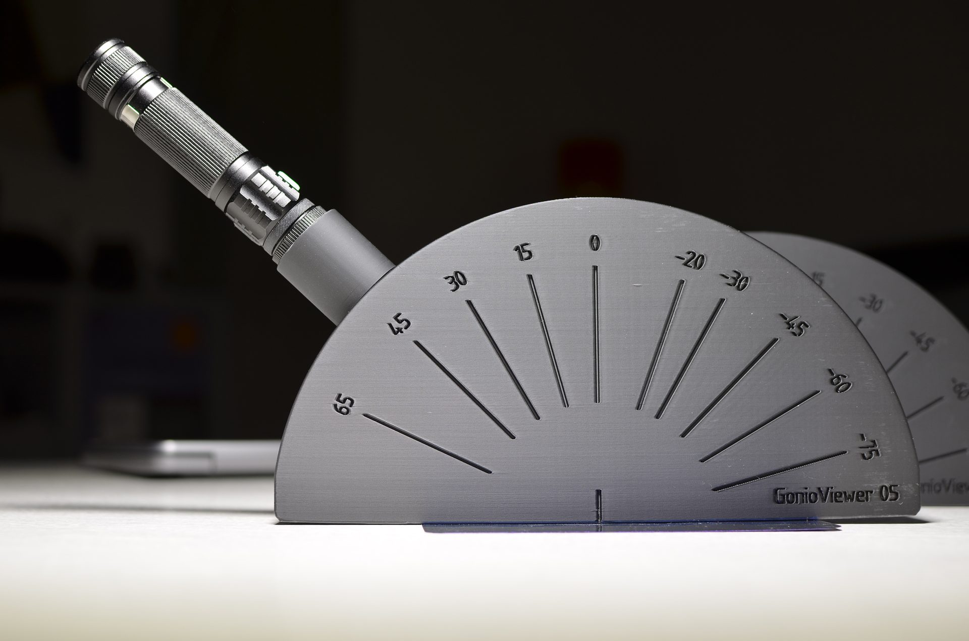
GonioViewer Experimental 05 corresponds to GonioViewer 03. In addition, holes are provided at 15°, -45° and -75°. These angles correspond to those for determining sparkle with the BYKmac. They are used to illuminate a panel to take black-and-white photos with the camera in the normal. These photos are used to calculate the sparkle values.
This GonioViewer 05 can also be used to simulate the second illumination of the X-Rite MA-98 and MA-T12. It has a borehole at 15° for the second illumination. The angles of difference at 15°, 45°, 60°, 80° and at -15°, -30°, -45°, -60° can be observed (Figure 6).
FIGURE 6–ǀ–GonioViewer 05 builds on version 03 with additional angles for evaluating sparkle characteristics.
More Geometries for the Sparkle
The illumination angles for determining the sparkle values were defined by BYK at random. The selection was based on the technical and mechanical possibilities in the BYKmac instrument. This is why the angles are placed on both sides of the normal: 15°, -45° and -75° from the normal.
In many cases, there is no difference depending on the side from which the light is coming. However, there are coated panels or injection moldings for which the direction plays a significant role, and differences do occur.
For the GonioViewer 06, we have therefore placed the illumination angles on both sides of the normal and also added two angles. With 15°, 30°, 45°, 60° and 75° from the normal, a better picture of the sparkle of the panel is obtained. The angle combination of 15°, 30° and 60° has proven to be better than the combination of 15°, 45° and 75° (Figure 7).
FIGURE 7–ǀ–GonioViewer 06 supports evaluation of sparkle and interference effects with added illumination angles from 15° to 75° on both sides of the normal.
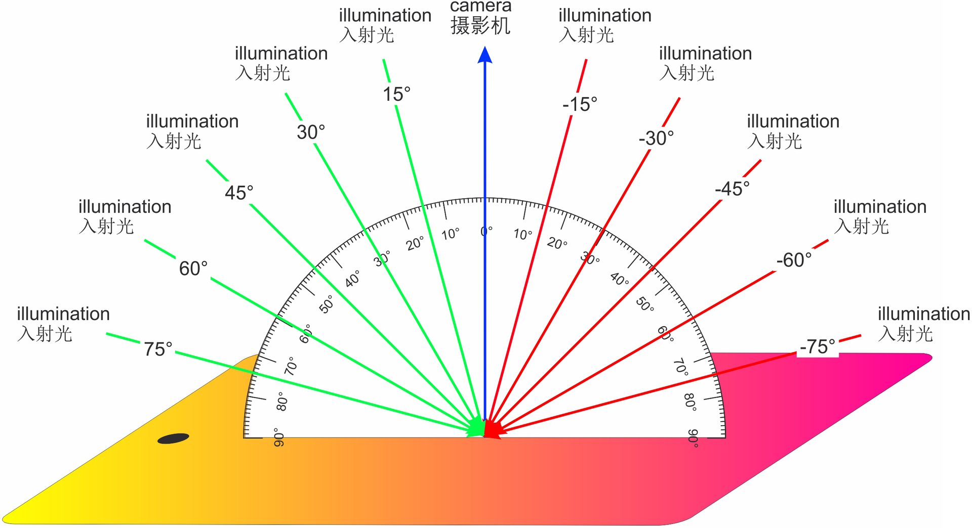
The interference and aspecular lines can also be simulated with GonioViewer 06: If you illuminate at 15°, 45° and 60° (or 75°) and observe at 15° from the respective angle, you can see the interference color shift. The 75° angle is unique and has not been implemented in any measuring instrument. If illuminated at 45°, the color gradient can be seen as one moves away from specular. The corresponding angles of difference are -30°, -15°, 15°, 30°, 45°, 60°, 75°, 105° and 120° from the angle of gloss at -45° (Figure 8).
FIGURE 8–ǀ–Visual assessment scenarios for interference pigments include the interference line, aspecular lines and tilt-based paths; GonioViewers address all.
Summary
The current geometries of portable measuring instruments are based on compilations that are over 30 years old. Until now, the suitability of these geometries, especially for interference pigments, has not been verified. Every day, interference pigments are measured with these instruments without the geometries being questioned and the measurement results being checked for plausibility.
The lack of geometries significantly limits instrumental color matching. The GonioViewer Experimental can be used to close the gaps for visual color matching. Since different requirements are placed on visual assessment, the versions of the GonioViewer can be adapted accordingly (Figure 6).
For more information, eMail info@wrcramer.de and mail@wolfmoritzcramer.de.